
TO46 Component Insertion and Automated PCB Electrical Testing Solutions
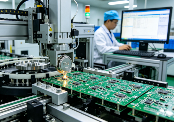
Article content
TO46 Component Insertion and Automated PCB Electrical Testing Solutions
If you've ever been responsible for scaling up production of optoelectronic components, you already know the challenge. TO46 packages are everywhere—in fiber optic transceivers, laser diodes, sensor modules, and a growing list of applications that demand high reliability in a compact form factor. But here's the thing. Getting these components from a reel or tray onto a PCB—and making sure they actually work—is not straightforward.
I've spent enough time around assembly lines to know that the transition from manual to automated handling of TO-series components is where a lot of production plans stumble. The leads are delicate. The alignment requirements are tight. And electrical testing? That's a whole separate challenge.
Let me walk you through what actually matters when you're implementing automated TO46 component insertion and PCB electrical testing solutions.
Understanding the TO46 Package and Its Applications
Let's start with what we're actually dealing with.
The TO46 is a metal-can package used extensively in the optoelectronics industry. It's a standard for housing laser diodes, photodiodes, and other optical components that require hermetic sealing. The package typically features 4 to 5 pins, though configurations can vary.
Current coaxial packaged lasers like TO56 and TO46 are widely used in optical communications and optical module applications. Eoptolink, for example, operates one of the largest fully automatic TO packaging and testing lines in Asia.
TO46 components are used in a wide range of applications: optical transceivers, industrial sensors, medical devices, aerospace systems, and automotive LiDAR. In PCB layout, designers must account for heat dissipation, mechanical alignment, and solder joint integrity.
The Challenge of Automated TO46 Component Insertion
Here's what makes TO46 components tricky to automate.
Multiple pins, variable alignment. The pins on a TO46 package typically range from 4 to 7, arranged in a circular pattern. But pin distributions vary by model and specification. Because the pins are long and thin, they're not always perfectly straight from root to tip, making insertion into a socket or PCB hole difficult.
Delicate leads. The pins are fine and can bend or break during handling. Automated systems must handle components gently while still achieving accurate alignment.
High precision requirements. Automated insertion machines typically achieve positioning accuracy of ±0.02mm. For TO46 components, that level of precision is non-negotiable.
Socket insertion. In testing applications, components must be inserted into test sockets for electrical characterization. This requires both mechanical alignment and electrical contact reliability.
Without automation, these steps are performed manually—which introduces variability, slows throughput, and increases the risk of damaged components.
Automated Insertion Solutions: What to Look For
The good news is that automated solutions exist and they work. Here's what a modern TO46 automated insertion system looks like.
The Core Process Flow
A high-precision TO46 automatic testing machine typically follows this workflow:
Material loading: Components are taken from a cap-sealing tray
Vision alignment: A CCD camera performs angle recognition and rotates the component to the specified angle
Lead straightening: The TO leads are automatically separated and straightened
Socket insertion: The component is inserted into a test socket
Coupling and testing: Optical and electrical tests are performed
Sorting: The component is removed from the socket and placed into the appropriate output tray based on test results
Some machines can process up to 1,200 components in a single batch, significantly improving test efficiency and yield while reducing the instability introduced by manual operations.
Key Technical Specifications
Let me give you some real numbers from a typical high-precision TO automatic testing machine:
Parameter | Specification |
UPH (Units Per Hour) | 800-900 pcs/h (varies by product) |
Rejection rate | <15‰ |
Insertion failure rate | <1‰ |
Socket lifespan | >20,000 insertions |
Lead straightening tool lifespan | 30,000-50,000 cycles |
Vision system | 1.3MP with blue light |
Pickup method | Vacuum nozzle |
A TO automatic testing machine can measure parameters including operating current (Icc), dark current (Id), monitor current, waveform amplitude, and focal length. Some systems can test up to 1,000 pieces of TO46 5-pin components at once.
Vision Systems and Alignment
Modern insertion systems rely on machine vision for alignment. A typical configuration uses two vision systems—one for component recognition and one for position verification. The vision system automatically recognizes the component orientation and controls the rotation to achieve the correct insertion angle.
Component Handling
For TO46 and similar packages, specialized handling equipment exists. The RTO-400, for example, is an automatic lead-forming and component transfer machine designed specifically for handling and feeding TO56, TO46, and TO38 components.
PCB Electrical Testing: From Insertion to Verification
Once components are inserted, the real work begins. Electrical testing is the gatekeeper that separates functional boards from scrap.
Types of PCB Electrical Testing
There are several approaches to automated PCB electrical testing:
Flying Probe Testing (FPT): An automated testing method where mobile electrical probes rapidly move across the PCB to contact specific test points. Flying probe testers are particularly effective for insertion-mounted boards. They can detect issues that are difficult to catch with visual inspection alone, including misplacement, bridging, shorts, and polarity errors.
In-Circuit Testing (ICT): Uses a fixed bed-of-nails fixture to contact test points. ICT can test four PCBs simultaneously in some configurations, delivering up to four times the throughput of conventional equipment. ICT verifies component values, continuity, and electrical performance before the unit is powered up.
Functional Testing (FCT): Validates the PCB's operation in real-world conditions.
Automated Optical Inspection (AOI): Detects visual defects such as scratches, voids, and misalignments. AOI is now standard equipment on SMT production lines.
Optical-Mechanical Alignment
Advanced electrical testing equipment now incorporates optical positioning and alignment techniques, enabling optical-mechanical closed-loop alignment that enhances positioning accuracy and testing reliability.
Automated Testing Integration
When you're running high-volume production, you need testing that's integrated with the rest of the line. Inline board handling systems can automate board alignment, high-voltage and high-current testing, and throughput management. Some systems can test multiple PCBs simultaneously to maximize throughput without sacrificing test coverage.
Integrated Solutions: Combining Insertion and Testing
Here's the thing. The most effective approach isn't insertion here and testing there. It's integrating both into a continuous workflow.
The high-precision TO automatic testing machine I described earlier is a perfect example. It combines three processes—component handling and insertion, optical and electrical testing, and sorting—into a single integrated system.
The integrated workflow looks like this:
Automated loading: Components are picked from trays
Vision alignment: CCD cameras ensure correct orientation
Lead preparation: Pins are straightened and separated
Socket insertion: Components are inserted into test sockets
Testing: Optical and electrical parameters are measured
Sorting: Components are automatically sorted into output trays based on test results
The system automatically handles edge cases. If a component can't be inserted properly, it's rejected and the next component is picked. Sensors detect whether the component is fully inserted and whether the press mechanism is functioning correctly. The system uses manual initial positioning with automatic operational positioning, with visual templates that can be configured for up to 20 different product models.
Real-World Application: Scaling Optoelectronic Production
Let me share an example that illustrates what integrated TO46 insertion and testing can deliver.
A manufacturer of optical transceiver modules was struggling with manual assembly and testing of TO46 components. Production was bottlenecked at the insertion and testing stations. Operators were manually placing components into test sockets, running tests one at a time, and manually sorting good from bad.
The company implemented an automated TO46 testing system that integrated component insertion, coupling, testing, and sorting. The system could process up to 900 components per hour. Rejection rates dropped to below 15‰, and insertion failures were under 1‰.
The result? Throughput increased by nearly 400% compared to manual operations. Labor requirements dropped from multiple operators to a single machine attendant. And quality improved because the automated system eliminated the variability that manual handling introduced.
The system was designed to be flexible—visual templates could be configured for different TO46 product variants, and the machine could be reprogrammed for different test parameters.
Frequently Asked Questions
What is a TO46 package?
The TO46 is a metal-can package used for housing laser diodes, photodiodes, and other optoelectronic components. It typically features 4 to 5 pins arranged in a circular pattern and requires hermetic sealing for reliable operation.
Why is automated insertion important for TO46 components?
TO46 components have delicate leads that are prone to bending. Manual insertion introduces variability, slows throughput, and increases the risk of damaged components. Automated insertion ensures consistent alignment, gentle handling, and high throughput.
What parameters does a TO46 automatic testing system measure?
Typical parameters include operating current (Icc), dark current (Id), monitor current, waveform amplitude, and focal length. More advanced systems can also measure breakdown voltage, responsiveness, and other performance characteristics.
What's the difference between flying probe testing and in-circuit testing?
Flying probe testing uses mobile probes that move to contact test points, making it flexible and cost-effective for prototypes and small batches. In-circuit testing uses a fixed bed-of-nails fixture and is faster for high-volume production.
How fast can an automated TO46 testing system run?
A typical high-precision system can process 800-900 components per hour. Cycle time, including loading, lead straightening, coupling, testing, and unloading, can be under 9 seconds per component.
Can these systems handle different TO46 product variants?
Yes. Modern systems use visual templates and configurable settings to handle different product models. Some systems support up to 20 different product configurations.
What's the typical rejection rate for automated TO46 insertion?
Well-tuned systems achieve rejection rates below 15‰ (1.5%) and insertion failure rates under 1‰ (0.1%).
Final Thoughts
Look, I've been around enough optoelectronic assembly lines to know that TO46 component handling and testing often get treated as an afterthought. "Just insert them and test them" is something I hear all the time. But the reality is that these components are delicate, alignment-critical, and performance-sensitive.
The difference between manual and automated TO46 insertion and testing isn't small. We're talking about throughput improvements of 300-400%. Rejection rates that drop from double-digit percentages to below 1.5%. Labor requirements that go from multiple operators to a single attendant.
The technology is proven. Vision-guided insertion works. Automated socket testing works. Integrated sorting works. The machines exist, the specifications are documented, and the ROI is clear.
If you're scaling production of TO46-based products, the question isn't whether to automate. The question is how fast you can get it done.
Project discussion
Discuss an automation requirement with our team
Share the workpiece, process sequence, layout, and interface requirements for a project-based technical review.